Paziņojums par privātumu: jūsu privātums mums ir ļoti svarīgs. Mūsu uzņēmums sola neatklāt jūsu personisko informāciju nevienai eksponācijai ar skaidrām atļaujām.
Modelis Nr.: NSO4GU3AB
Transports: Ocean,Air,Express,Land
Maksājuma veids: L/C,T/T,D/A
Incoterm: FOB,EXW,CIF
4GB 1600MHz 240-pin ddr3 udimm
Revīzijas vēsture
|
Revision No. |
History |
Draft Date |
Remark |
|
1.0 |
Initial Release |
Apr. 2022 |
|
![]()
Informācijas tabulas pasūtīšana
|
Model |
Density |
Speed |
Organization |
Component Composition |
|
NS04GU3AB |
4GB |
1600MHz |
512Mx64bit |
DDR3 256Mx8 *16 |
Apraksts
Hengstar Unbuched DDR3 SDRAM DIMM (bez divkāršo datu pārraides ātruma sinhronās dram Dual in-līnijas atmiņas moduļi) ir mazas jaudas, ātrgaitas operācijas atmiņas moduļi, kas izmanto DDR3 SDRAM ierīces. NS04GU3AB ir 512m x 64 bitu divu rangu 4GB DDR3-1600 CL11 1,5 V SDRAM nepamatots DIMM produkts, pamatojoties uz sešpadsmit 256m x 8 bitu FBGA komponentiem. SPD tiek ieprogrammēts JEDEC standarta latentuma DDR3-1600 laikā 11-11-11 pie 1,5 V. Katrā 240 kontaktu DIMM izmanto zelta kontakta pirkstus. SDRAM Unbuffed DIMM ir paredzēts izmantošanai kā galvenā atmiņa, kad to uzstāda tādās sistēmās kā personālie datori un darbstacijas.
Iespējas
Power Piegāde: VDD = 1,5 V (1,425 V līdz 1,575 V)
VDDQ = 1,5 V (1,425 V līdz 1,575 V)
800MHz FCK 1600MB/sek/tapa
8 Neatkarīgā iekšējā banka
Programmējamais CAS latentums: 11, 10, 9, 8, 7, 6
Programmējamais piedevu latentums: 0, cl - 2 vai cl - 1 pulkstenis
8-bitu priekšnoteikums
Burst garums: 8 (starpnozaru bez jebkādas robežas, secīga ar sākuma adresi tikai “000”), 4 ar tccd = 4, kas neļauj nemanāmi lasīt vai rakstīt [vai nu lidojumā, izmantojot A12 vai MRS]
Bi virziena diferenciālo datu strobe
Pasaules (sevis) kalibrēšana; Iekšējā sevis kalibrēšana caur ZQ PIN (RZQ: 240 omi ± 1%)
on Die pārtraukšana, izmantojot ODT PIN
Visparage atsvaidzes periods 7,8US zemāks par Tcase 85 ° C, 3,9US 85 ° C <tcase <95 ° C
Asinhronā atiestatīšana
Parādāmais datu-izvades piedziņas stiprums
Fly-the topology
PCB: augstums 1,18 ”(30 mm)
RoHs atbilstošs un bez halogēna
Galvenie laika parametri
|
MT/s |
tRCD(ns) |
tRP(ns) |
tRC(ns) |
CL-tRCD-tRP |
|
DDR3-1600 |
13.125 |
13.125 |
48.125 |
2011/11/11 |
Adreses tabula
|
Configuration |
Refresh count |
Row address |
Device bank address |
Device configuration |
Column Address |
Module rank address |
|
4GB |
8K |
32K A[14:0] |
8 BA[2:0] |
2Gb (256 Meg x 8) |
1K A[9:0] |
2 S#[1:0] |
Tapu apraksti
|
Symbol |
Type |
Description |
|
Ax |
Input |
Address inputs: Provide the row address for ACTIVE commands, and the column |
|
BAx |
Input |
Bank address inputs: Define the device bank to which an ACTIVE, READ, WRITE, or |
|
CKx, |
Input |
Clock: Differential clock inputs. All control, command, and address input signals are |
|
CKEx |
Input |
Clock enable: Enables (registered HIGH) and disables (registered LOW) internal circuitry |
|
DMx |
Input |
Data mask (x8 devices only): DM is an input mask signal for write data. Input data is |
|
ODTx |
Input |
On-die termination: Enables (registered HIGH) and disables (registered LOW) |
|
Par_In |
Input |
Parity input: Parity bit for Ax, RAS#, CAS#, and WE#. |
|
RAS#, |
Input |
Command inputs: RAS#, CAS#, and WE# (along with S#) define the command being |
|
RESET# |
Input |
Reset: RESET# is an active LOW asychronous input that is connected to each DRAM and |
|
Sx# |
Input |
Chip select: Enables (registered LOW) and disables (registered HIGH) the command |
|
SAx |
Input |
Serial address inputs: Used to configure the temperature sensor/SPD EEPROM address |
|
SCL |
Input |
Serial |
|
CBx |
I/O |
Check bits: Used for system error detection and correction. |
|
DQx |
I/O |
Data input/output: Bidirectional data bus. |
|
DQSx, |
I/O |
Data strobe: Differential data strobes. Output with read data; edge-aligned with read data; |
|
SDA |
I/O |
Serial |
|
TDQSx, |
Output |
Redundant data strobe (x8 devices only): TDQS is enabled/disabled via the LOAD |
|
Err_Out# |
Output (open |
Parity error output: Parity error found on the command and address bus. |
|
EVENT# |
Output (open |
Temperature event: The EVENT# pin is asserted by the temperature sensor when critical |
|
VDD |
Supply |
Power supply: 1.35V (1.283–1.45V) backward-compatible to 1.5V (1.425–1.575V). The |
|
VDDSPD |
Supply |
Temperature sensor/SPD EEPROM power supply: 3.0–3.6V. |
|
VREFCA |
Supply |
Reference voltage: Control, command, and address VDD/2. |
|
VREFDQ |
Supply |
Reference voltage: DQ, DM VDD/2. |
|
VSS |
Supply |
Ground. |
|
VTT |
Supply |
Termination voltage: Used for control, command, and address VDD/2. |
|
NC |
– |
No connect: These pins are not connected on the module. |
|
NF |
– |
No function: These pins are connected within the module, but provide no functionality. |
Piezīmes : Tapu apraksta tabula Zemāk ir visaptverošs visu iespējamo tapu saraksts visiem DDR3 moduļiem. Visas uzskaitītās tapas var netiek atbalstīts šajā modulī. Informāciju, kas raksturīga šim modulim, skatiet PIN piešķīrumu.
Funkcionālā bloka diagramma
4GB, 512MX64 modulis (X8 2Rank)


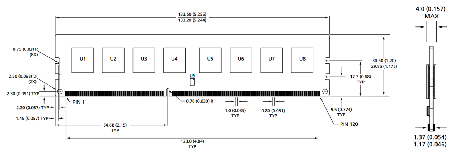
Moduļa izmēri
Skats no priekšas

Skats no priekšas

Piezīmes:
1. Visi izmēri ir milimetros (collas); Maksimālais/min vai tipisks (tips), kur norādīts.
2.Polerance uz visām izmēriem ± 0,15 mm, ja nav norādīts citādi.
3. Dimensijas diagramma ir paredzēta tikai atsaucei.
Produktu kategorijas : Rūpnieciski viedie moduļa piederumi


Paziņojums par privātumu: jūsu privātums mums ir ļoti svarīgs. Mūsu uzņēmums sola neatklāt jūsu personisko informāciju nevienai eksponācijai ar skaidrām atļaujām.

Aizpildiet vairāk informācijas, lai varētu sazināties ar jums ātrāk
Paziņojums par privātumu: jūsu privātums mums ir ļoti svarīgs. Mūsu uzņēmums sola neatklāt jūsu personisko informāciju nevienai eksponācijai ar skaidrām atļaujām.